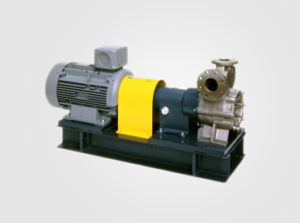
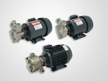
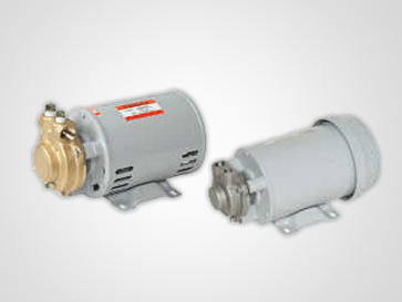
K Series
KED-V / KHD / KHD-V / KWD
- General industrial applications
- Circulation of hot and cold water /media
- Integrated with a variety of OEM machines
Features
- Lead-free copper components, friendly to people and the environment
- Amount of copper leaching onto water < 0.005 mg/L (standard value 0.01 mg/L)
- Stable and reliable performance at small flow rates
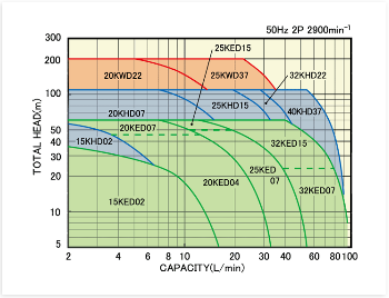
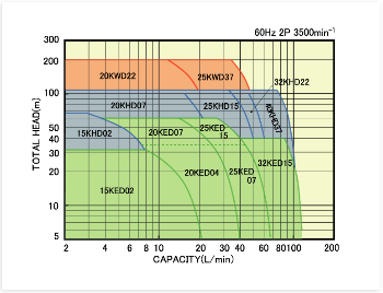
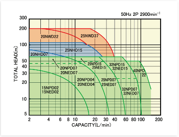
Performance Curve
Specification data
| Series name |
KED-V |
KHD-V | KWD-V |
| Total head | Max. 60 m | Max. 110 m | Max. 200 m |
| Flow rate | Max. 110 L/min | Max. 50 L/min | |
| Liquid temp. | ~ 120℃ (standard) / ~150℃ (-V) | ||
Material
| Casing / cover | CAC911 | ||
| Impeller | SS403 | ||
| Mech. seal | Ceramic – Carbon, NBR (standard) SiC – Carbon, FKM (-V) |
||
| O-ring | NBR (standard) / FKM (-V) | ||
| Shaft | SS316 | ||
Motor data
| Single phase / Open drip proof motor |
50Hz/60Hz: 100/110/115/200/220/230V 0.3~0.56kW IP22, Insu. class: E.PS-E | |
| Three phase / Total enclosed fan cooled motor |
50Hz: 200V 60Hz: 200/220V 0.31~3.7kW IP44, Insu. class: E.PS-E | |
| Three phase increased safety motor (A) |
50Hz: 200V 60Hz: 200/220V 0.31~3.7kW IP44, Insu. class: E.PS-E | |
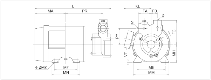
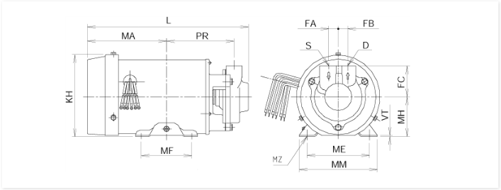
Dimensions
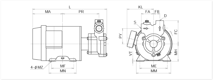
| Model | kW | S | D | PR | PY | FA | FB | FC | MH | L | MA | ME | MF | MM | MN | MZ | VT | KL | Weight |
| 15KED02Z | 0.31 | Rc 1/2 | Rc 3/8 | 146 | 52 | 45 | 21 | 81 | 71 | 298 | 121 | 112 | 90 | 140 | 110 | 7×8 | 2.3 | 107 | 9.5 |
| 15KED04Z | 0.56 | Rc 1/2 | Rc 3/8 | 146 | 52 | 45 | 21 | 81 | 71 | 298 | 121 | 112 | 90 | 140 | 110 | 7×8 | 2.3 | 107 | 9.5 |
| 20KED04Z | 0.56 | Rc 3/4 | Rc 1/2 | 146.5 | 63 | 50 | 25 | 95 | 71 | 299.5 | 121 | 112 | 90 | 140 | 110 | 7×8 | 2.3 | 107 | 12 |
| 20KED07Z | 0.975 | Rc 3/4 | Rc 1/2 | 140 | 63 | 50 | 25 | 95 | 80 | 320 | 148 | 125 | 100 | 165 | 130 | 10×8 | 4.5 | 146 | 18 |
| 25KED07Z | 0.975 | Rc 1 | Rc 3/4 | 140 | 70 | 60 | 25 | 105 | 80 | 326.5 | 148 | 125 | 100 | 165 | 130 | 10×8 | 4.5 | 146 | 22 |
| 25KED15Z | 1.95 | Rc 1 | Rc 3/4 | 163 | 70 | 60 | 28 | 105 | 90 | 356 | 154.5 | 140 | 125 | 176 | 149 | 10×12 | 10 | 156 | 26 |
| 32KED15Z | 1.95 | Rc 1 1/4 | Rc 1 | 167.5 | 80 | 65 | 35 | 120 | 90 | 366 | 154.5 | 140 | 125 | 176 | 149 | 10×12 | 10 | 156 | 27 |
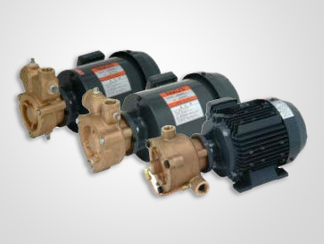
N Series
NPD / NED-V / NHD-V / NWD
- General industrial applications
- Circulation of hot and cold water /media
- Integrated with a variety of OEM machines
- Pure water and chemical liquid supply
Features
- Stable and reliable performance at small flow rates
- Radically reduce footprint of OEM equipment
- SiC x special carbon mechanical seal (model NPD-J)
- Available for pure water (low-viscosity liquid) applications
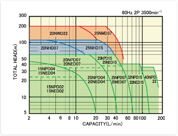
Performance Curve
Specification data
| Series name | NPD (Self priming) |
NPD-J | NED-V (Self priming) |
NHD-V | NWD |
| Total head | Max. 60 m | Max. 110 m | Max. 200 m | ||
| Flow rate | Max. 130 L/min | Max. 50 L/min | Max. 52 L/min | ||
| Liquid temperature | ~ 90℃ | ~ 80℃ | ~ 150℃ | ~ 90℃ | |
Material
| Series name | NPD (Self priming) |
NPD-J | NED-V (Self priming) |
NHD-V | NWD |
| Casing & cover | SCS13 | SCS14 | SCS13 | ||
| Impeller | SS304 | SS316 | SS304 | ||
| Mechanical seal | SiC- SiC, PTFE | SiC- Carbon, FKM | SiC- Carbon, FKM | SiC- Carbon, FKM | SiC- SiC, PTFE |
| O-ring | PTFE | FKM | PTFE | ||
| Shaft | SS316L | ||||
Motor data
| Single phase / Open drip proof motor |
50Hz/60Hz: 100/110/115/200/220/230V 0.3~0.56kW IP22, Insu. class: E.PS-E | |
| Three phase / Total enclosed fan cooled motor |
50Hz: 200V 60Hz: 200/220V 0.31~3.7kW IP44, Insu. class: E.PS-E | |
| Three phase increased safety motor (A) |
50Hz: 200V 60Hz: 200/220V 0.31~3.7kW IP44, Insu. class: E.PS-E | |
Dimensions
| Model | kW | S | D | PR | PY | FA | FB | FC | MH | L | MA | ME | MF | MM | MN | MZ | VT | KL | Weight |
| 15NED02Z | 0.31 | Rc 1/2 | Rc 3/8 | 146 | 52 | 45 | 21 | 81 | 71 | 298 | 121 | 112 | 90 | 140 | 110 | 7×8 | 2.3 | 107 | 9.5 |
| 20NED04Z | 0.56 | Rc 3/4 | Rc 1/2 | 146.5 | 63 | 50 | 25 | 95 | 71 | 299.5 | 121 | 112 | 90 | 140 | 110 | 7×8 | 2.3 | 107 | 12 |
| 20NED07Z | 0.975 | Rc 3/4 | Rc 1/2 | 140 | 63 | 50 | 25 | 95 | 80 | 320 | 148 | 125 | 100 | 165 | 130 | 10×8 | 4.5 | 146 | 18 |
| 25NED07Z | 0.975 | Rc 1 | Rc 3/4 | 140 | 70 | 60 | 28 | 105 | 80 | 326.5 | 148 | 125 | 100 | 165 | 130 | 10×8 | 4.5 | 146 | 22 |
| 25NED15Z | 1.95 | Rc 1 | Rc 3/4 | 163 | 70 | 60 | 28 | 105 | 90 | 356 | 154.5 | 140 | 125 | 176 | 149 | 10×12 | 10 | 156 | 26 |
| 32NED15Z | 1.95 | Rc 1/4 | RC 1 | 167.5 | 80 | 65 | 35 | 120 | 90 | 366 | 154.5 | 140 | 125 | 176 | 149 | 10×12 | 10 | 156 | 27 |
D Series
DKL / DKH / DNL / DNH
- General industrial applications
- Circulation of hot and cold water /media
- Integrated with a variety of OEM machines
- Chemical liquid supply
Features
- Lead-free copper components, friendly to
- people and the environment
- Amount of copper leaching onto water < 0.005 mg/L (standard value 0.01 mg/L)
- Stable and reliable performance at small flow rates
Performance Curve
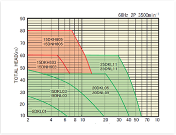
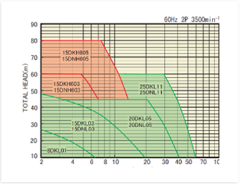
Specification data
| Series name |
DKL / DKH | DNL / DNH |
| Total head | Max. 110m | |
| Flow rate | Max. 75 L/min | |
| Liquid temp. | -20 to 120℃ | |
Material
| Casing / cover | Lead-free copper | SCS14 |
| Impeller | SS304 | |
| Mechanical seal | SiC – Carbon | |
| O-ring | FKM | |
| Shaft | SS316 | |
Motor data
| Single phase / Open drip proof motor |
50Hz / 60Hz 100V 0.37 to 0.56kW | IP22, Insu. class: E.PS-E |
| Three phase / Total enclosed fan cooled motor |
50Hz: 200/380/400/415 | |
| 60Hz: 200/220/380/400/440/460 | ||
| IP54, Insu. class: E.PS-E | ||
Dimensions
| Model | kW | S | D | PR | FA | FB | FC | MH | L | MA | ME | MF | MM | MZ | VT | KH | Weight |
| 8DKL01 | 0.1 | Rc 1/4 | Rc 1/4 | 94 | 16 | 16 | 25 | 56 | 171 | 77 | 70 | 43 | 90 | 6.5 | 5 | 90 | 7 |
| 15DKL03 | 0.37 | Rc 1/2 | Rc 3/8 | 120 | 16 | 14 | 50 | 71 | 256.5 | 110 | 112 | 90 | 140 | 7×8 | 2.3 | 139 | 8 |
| 20DKL05 | 0.55 | Rc 3/4 | Rc 1/2 | 120 | 17 | 17 | 55 | 71 | 255.5 | 110 | 112 | 90 | 140 | 7×8 | 2.3 | 138 | 9 |
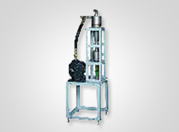
LAX Hydro Vacuum Cleaner
Introduction
The LAX is a portable wet-to-dry filtration cleaner and can even filter coolant while the machine is in operation.
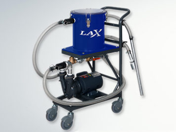
Features for LAX Hydro Vacuum Cleaner
- Easy operation
Runs on single phase power and is portable for use with multiple machines
- No downtime
The LAX does not reduce tank coolant level, therefore It can be used while the machine is running - Can Suck Air
There is no need for an air supply and as the pump can suck air, the unit is able to dry sludge after cleaning the tank for easy disposal.
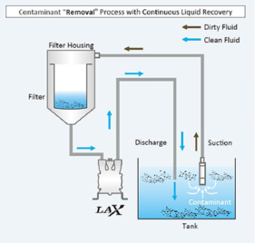
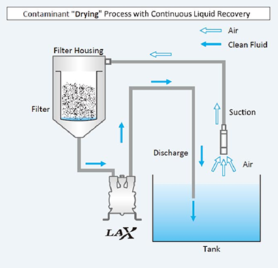
Flow Diagram
Case Studies
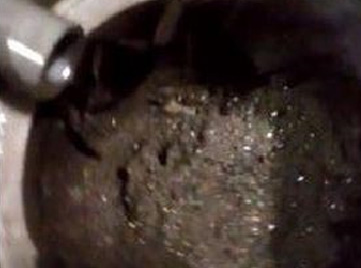
| Case Study 1: Centerless Grinding Machine | |
| Material | Steel |
| Machine | Centerless Grinding Machine with 100L Tank |
| Sludge Collection Time | 10 min |
| Dehydration time | 10 min |
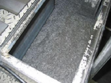
Before
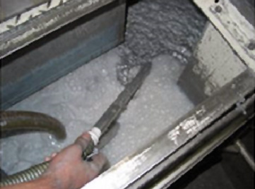
Cleaning
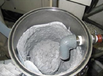
Dried Sludge
| Case Study 2: Running Machining Center | |
| Material | Aluminum |
| Sludge Collection Time | 10 min |
| Dehydration time | 2 min |
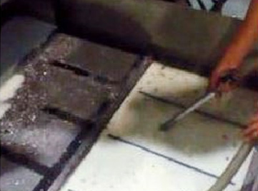
Cleaning
Dehydration
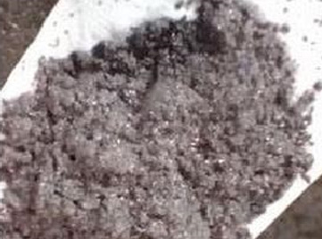
Dried Sludge
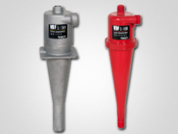
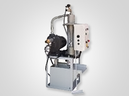
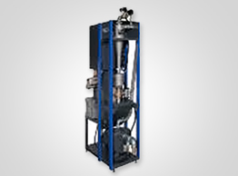
VDF Vortex Dynamic Filter
Centrifugal coolant filtration Nikuni VDF Hydro-Cyclone Filter:- No waste! | No filtration media! | No maintenance!
Introduction
The Vortex Dynamic Filter is a media free coolant filtration system which achieves filtration through centrifugal force eliminating the ;need for disposable paper or cartridge filters.
Features for VDF Vortex Dynamic Filter
- Filter replacement is not necessary as filtration is achieved through centrifugal force
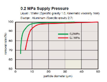
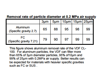
- Can remove 90% of 10μm sludge for water based coolant No bubbles or foam is produced.
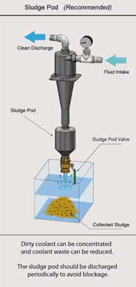
- Contaminants are concentrated in the sludge pod and once removed they cannot return to the coolant tank
Other Models :-

VDF Units
C-CAT
C-JAGUAR
NAX-CS
Highlights
- Wide range of sizes (10-300L/min)
- Media-free operation: No Industrial waste & No maintenance
- Highly efficient & precise filtration (10um 90%)
- No Foaming by trapped air (with Sludge Pod)
- Simple disposal of concentrated sludge
| Model | Process Fluid |
| CL-10LW | 10L/min. |
| CL-20LW | 20L/min. |
| CL-30LW | 30L/min. |
| CL-50LW | 50L/min. |
| CL-70LW | 70L/min. |
| CL-100LW | 100L/min. |
| CL-200LW | 200L/min. |
| CL-300LW | 300L/min. |
Advantages
- Protect machine tools (sliding surface, coolant pump, rotary joint etc.)
- Reduce running cost (with sludge Pod)
- Reduce tank cleaning frequency (with sludge Pod)
- Reduce Fluid replacement Frequency (with sludge Pod)
- Improve the yield of manufacturing (with sludge Pod)
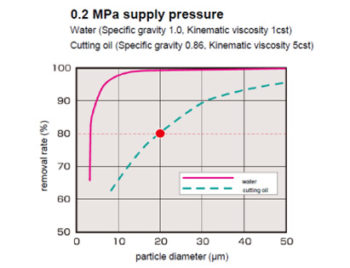
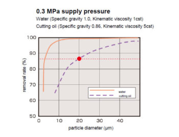
VDF Removal Rate
Removal Rate Comparison Between Water And Oil
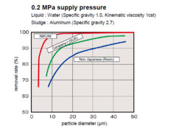
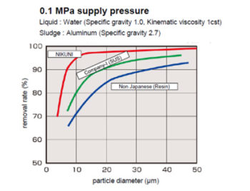
Removal Rate Comparison With Other Companies
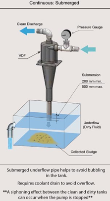
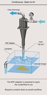
Underflow Options
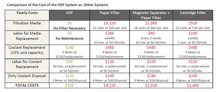
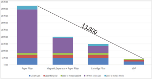
Saving of up to $3,800 a year!*
No replacement filters | No maintenance to replace filter | Reduced coolant replacement/disposal | Improved accuracy
Lorem Ipsum is simply dummy text of the printing and typesetting industry. Lorem Ipsum has been the industry’s standard dummy text ever since the 1500s, when an unknown printer took a galley of type and scrambled it to make a type specimen book. It has survived not only five centuries, but also the leap into electronic type
Nikuni KTM Micro Bubble Pumps at a glance
NIKUNI, a Japanese company which has produced high quality equipment for various water related industries has developed a unique compact micro-bubble generator for use in dissolved air flotation systems, called the KTM.
The KTM has a highly precise and sophisticated pumping mechanism that can generate massive quantities of micro-bubbles by means of three hydro-dynamic principles:
- Negative pressure sucking both air and water simultaneously from each port
- Air is effectively transferred to the water
- Pressurized, air-enriched water is discharged
The pressurized, air-enriched water is transferred into the bottom of the dissolved air flotation tank from where it makes a bubble sparkling formation, spreading and rising up to the water surface pulling fine material, oils, fats, fibres and more with it to form a sludge mat. This mat is then skimmed.

Features for DAF Applications
- High rate of suspended solids removal
- Supplying a highly dense Microbubble output
- Highly consistent dissolved air flotation
- Fine adjustments not necessary when operation or start up
- Easily retrofit to pre-existing systems
- Small installation footprint
- Minimum power consumption
- Low power required for KTM (no compressor required)
- Easy maintenance and minimum operational cost
- Compact and simple pump structure
- Quiet operation
- No compressor, level controls, saturation tank required
| Features of Dissolved Air Floatation with NIKUNI KTM | |
| Equipment savings | No air compressor (saves energy, reduces noise, no compressor oil contamination into DAF flow). No large dissolving tank No static diffuser |
| Operational cost savings | Smaller pump compared to conventional systems, up to 67% lower energy consumption |
| Skilled staff savings | One time system setup and simple control No level control End-users can allocate skilled staff resources to other activities |
| Maintenance savings | Longer pump life Fewer parts and very simple to maintain |
| Reliability | Excellent track record KTM end-user clients include many internationally reknown brands. |
| Design flexibility | Very large range of sizes and materials to fit perfectly with end-user requirements. |
| Innovative | The system is much smaller, simpler, yet much higher performing compared to conventional systems. |
Other Models :-
KTM20, KTM25, KTM32, KTM40
KTM50-1, KTM50-2, KTM50-3